Breadboard Basics: Build Circuits Without Soldering
Learn how a breadboard works, how its rows and power rails are connected, and how to build simple circuits without soldering. Perfect for beginners starting with LEDs, sensors, Arduino, ESP32, Raspberry Pi Pico, and other electronics projects.
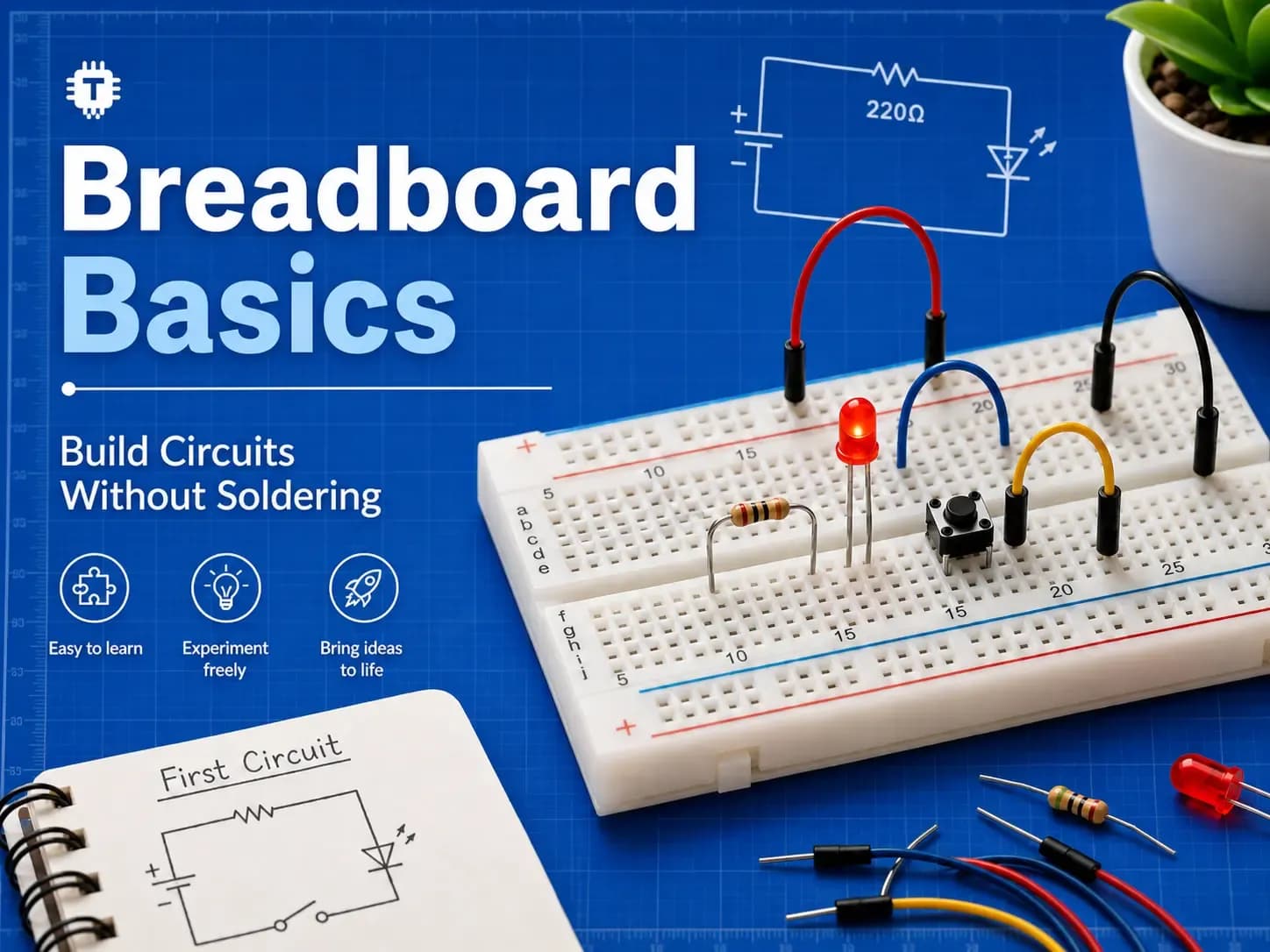
A breadboard is one of the most useful tools in electronics. It lets you build and test circuits without soldering, which makes it perfect for learning, experimenting, and prototyping.
Instead of permanently joining components with solder, you can simply push wires and component legs into the breadboard holes. Want to change a resistor? Move a wire? Add a sensor? Just unplug and rearrange. No soldering iron, no fumes, no dramatic smoke ceremony.
For beginners, a breadboard is the electronics version of a rough notebook. You can try ideas, make mistakes, fix them, and keep building.
What Is a Breadboard?
A breadboard is a reusable plastic board with many small holes. Inside the board are metal clips that connect certain holes together.
When you insert a jumper wire, resistor leg, LED, or component pin into a hole, it touches the metal clip underneath. This creates an electrical connection.
The important thing to understand is this:
Not every hole is connected to every other hole.
Breadboards have a hidden internal layout. Once you understand that layout, breadboarding becomes much easier.
Why Use a Breadboard?
Breadboards are mainly used for prototyping, which means building a temporary version of a circuit before making it permanent.
You can use a breadboard to:
Test a circuit before soldering it
Try different resistor or capacitor values
Build Arduino, ESP32, and Raspberry Pi Pico projects
Connect sensors, LEDs, buttons, and modules
Debug a circuit step by step
Reuse components again and again
This makes breadboards especially useful for students, makers, hobbyists, repair work, and anyone learning electronics from scratch.
Main Parts of a Breadboard
Most standard breadboards have three main sections:
Power rails
Terminal strips
Center gap
Let’s look at each one.
1. Power Rails
The long lines of holes along the sides of a breadboard are called power rails.
They are usually marked with red and blue lines.
The red rail is commonly used for positive voltage, such as:
5V
3.3V
Battery positive
The blue or black rail is commonly used for:
GND
0V
Battery negative
Power rails make it easy to distribute power across your circuit. Instead of running power wires to every single component from your battery or development board, you connect power once to the rail and then take power from that rail wherever needed.
Important: Some Power Rails Are Split
On many breadboards, the power rails are split in the middle. This means the top half and bottom half are not connected internally.
If your circuit looks correct but nothing powers on, check the power rails. You may need to connect the two halves using a jumper wire.
This tiny detail causes a surprising number of beginner headaches. It is the breadboard’s favorite little trapdoor.
2. Terminal Strips
The main working area of the breadboard is made of rows of holes. These rows are usually numbered.
On a typical breadboard, each group of five holes in a row is connected internally.
For example:
A1, B1, C1, D1, and E1 are connected together.
On the other side of the center gap:
F1, G1, H1, I1, and J1 are connected together.
But the left group and right group are not connected across the center gap.
So:
A1 and C1 are connected
A1 and E1 are connected
A1 and F1 are not connected
E1 and F1 are not connected
This layout allows you to place components and wires into shared connection points without soldering.
3. Center Gap
The gap running down the middle of the breadboard separates the two sides.
This gap is useful for placing integrated circuits, also called ICs or chips. ICs are designed to sit across the gap, with one row of pins on one side and the other row of pins on the opposite side.
This prevents pins on opposite sides of the chip from being accidentally connected together.
Without the center gap, many ICs would be shorted immediately. That is less “electronics learning” and more “instant sadness with plastic.”
Common Breadboard Accessories
To build circuits on a breadboard, you will usually use:
Jumper wires for making connections
Resistors for limiting current or setting voltage levels
LEDs for visual output
Push buttons for input
Capacitors for filtering and timing
Sensors for detecting light, temperature, motion, distance, and more
Microcontroller boards like Arduino, ESP32, Raspberry Pi Pico, and similar boards
Power sources such as USB, batteries, bench power supplies, or development board power pins
For most beginner projects, male-to-male jumper wires are the most useful type for breadboards.
Your First Breadboard Circuit: Lighting an LED
A simple LED circuit is one of the best ways to learn how a breadboard works.
It teaches four important ideas:
Power
Ground
Polarity
Current limiting
Components Needed
You will need:
1 breadboard
1 LED
1 resistor, usually between 220Ω and 1kΩ
Jumper wires
3.3V or 5V power source
Understanding LED Polarity
LEDs have polarity. This means they must be connected the correct way.
An LED has two legs:
The longer leg is usually positive, called the anode
The shorter leg is usually negative, called the cathode
The flat edge on the LED body usually marks the negative side.
If the LED is connected backwards, it will not light up.
Why the LED Needs a Resistor
An LED should not be connected directly across power and ground.
A resistor is used in series with the LED to limit current. Without a resistor, too much current can flow through the LED, which may damage it.
Think of the resistor as a small traffic controller for electrons. It keeps the current from stampeding through the LED gate.
Basic LED Breadboard Connection
Here is the basic connection:
Connect the positive supply, such as 5V or 3.3V, to one side of the resistor.
Connect the other side of the resistor to the LED’s longer leg.
Connect the LED’s shorter leg to GND.
Power the circuit.
If everything is connected correctly, the LED should turn on.
If it does not turn on, check:
Is the LED backwards?
Is the resistor actually in series?
Is the breadboard rail powered?
Are the power rails split?
Are the jumper wires fully inserted?
How Breadboard Connections Work
The golden rule of breadboards is:
Holes in the same connected row are electrically the same point.
If two component legs are placed in the same connected row, they are connected together.
This is useful, but it can also cause mistakes.
For example, if both legs of a resistor are placed in the same connected row, the resistor is bypassed. The circuit behaves as if the resistor is not doing anything.
The same problem can happen with LEDs, capacitors, and switches.
Beginner Tip
Place component legs in different rows unless you intentionally want them connected.
This one habit saves a lot of debugging time.
Using Breadboards with Arduino, ESP32, and Raspberry Pi Pico
Breadboards are commonly used with microcontroller boards.
A typical setup looks like this:
Connect the board’s 5V or 3.3V pin to the breadboard positive rail.
Connect the board’s GND pin to the breadboard ground rail.
Place LEDs, buttons, sensors, or modules on the breadboard.
Use jumper wires to connect them to GPIO pins.
This makes it easy to test circuits before building a permanent version.
Common Ground Is Important
When using a breadboard with a microcontroller, all parts of the circuit usually need to share a common ground.
For example, if a sensor is powered from one source and your microcontroller is powered from another, their GND connections usually need to be connected together.
Without a common ground, signals can behave strangely or not work at all.
Breadboard Safety Tips
Breadboards are beginner-friendly, but it is still important to build carefully.
Follow these basic safety tips:
Disconnect power before changing wires
Use a resistor with LEDs
Check polarity for LEDs, capacitors, batteries, and modules
Do not connect 5V or 3.3V directly to GND
Avoid forcing thick wires into breadboard holes
Keep wiring neat and easy to trace
Use low voltages when learning, such as 3.3V or 5V
Do not use breadboards for mains AC voltage
Avoid high-current circuits on breadboards
Breadboards are great for low-power electronics, sensors, logic circuits, and microcontroller projects.
They are not suitable for high-current motors, heaters, mains voltage, or heavy power electronics.
Common Breadboard Mistakes
1. Power Rail Is Not Actually Powered
Sometimes you connect power to one rail but use another rail that is not connected. Always check where your power is actually going.
2. Split Power Rails Are Not Bridged
Some breadboards have a break in the middle of the power rails. Use jumper wires to connect both halves if needed.
3. Component Legs Are in the Same Row
If both legs of a component are in the same connected row, the component may be shorted or ignored by the circuit.
4. LED Is Backwards
LEDs only work in one direction. If it does not light up, try reversing it.
5. No Resistor with LED
An LED needs a current-limiting resistor. Skipping it can damage the LED or your board.
6. Loose Jumper Wires
Poor-quality or loose jumper wires can cause unreliable circuits. If your circuit works only when you press or wiggle a wire, suspect the jumper.
7. Wrong GPIO Pin
When using Arduino, ESP32, or Pico boards, make sure your wire is connected to the same pin used in your code.
Quick Debugging Checklist
If your breadboard circuit is not working, check these first:
Is the power supply connected?
Are positive and GND connected correctly?
Are the power rails split?
Is the LED polarity correct?
Is the resistor in series with the LED?
Are component legs placed in separate rows?
Is the microcontroller GND connected to circuit GND?
Are jumper wires fully inserted?
Is the code using the correct pin?
Is the component damaged?
Most breadboard issues are simple wiring problems hiding in plain sight.
Debugging is not magic. It is just careful detective work with fewer fingerprints and more jumper wires.
When Should You Move Beyond a Breadboard?
A breadboard is excellent for testing and learning, but it is not meant to be the final form of every project.
You should consider moving beyond a breadboard when:
The circuit needs to run for a long time
The project will be moved around
There are too many loose wires
The circuit needs to fit inside an enclosure
You want a stronger and cleaner build
You are making a product, kit, or repeatable design
For more permanent builds, you can use:
Perfboard
Stripboard
Soldered prototype board
Custom PCB
Screw terminal boards
Connector-based wiring
Breadboard vs PCB
A breadboard is temporary and reusable.
A PCB is permanent and purpose-built.
Use a breadboard when you are experimenting, testing, or learning.
Use a PCB when the circuit is finalized and needs to be reliable, compact, and repeatable.
The breadboard is your circuit’s sketchbook. The PCB is the final printed map.
Recommended Beginner Breadboard Projects
Once you understand the basics, try these small projects:
Light an LED
Control an LED with a push button
Build a traffic light using three LEDs
Read a potentiometer with Arduino
Connect an LDR light sensor
Use a temperature sensor
Control a buzzer
Build a simple ESP32 sensor circuit
Display sensor readings on an OLED module
Start small. Then combine parts slowly. Electronics becomes much easier when each small block makes sense.
Final Thoughts
A breadboard is one of the best starting points for learning electronics. It lets you build circuits without soldering, experiment freely, and understand how components connect in real life.
Once you understand the hidden row connections, power rails, center gap, and common beginner mistakes, breadboards become much less confusing.
Start with a simple LED. Add a resistor. Add a button. Then connect a sensor. Step by step, your breadboard becomes a tiny playground for real-world electronics.
Every circuit begins as an idea. A breadboard gives that idea a place to blink, beep, measure, and come alive.
Suggested Tags
Breadboard, Electronics Basics, Beginner Electronics, Arduino, ESP32, Raspberry Pi Pico, Prototyping, Jumper Wires, LED Circuit, DIY Electronics